Arduino 3.3V version with IL-LORA1272 Demo 教學
HI
大家好…因為最近有太多的朋友在問小編如何運用iForglab的LORA module並透過Arduino的方式來跟溝通。
我來跟各位作一個解釋,我們已經把對應的LORA module的範例程式已經放上Github了。
https://github.com/iFrogLab/IL-LORA1272/tree/master/Samples-Arduino/arduino_LORA
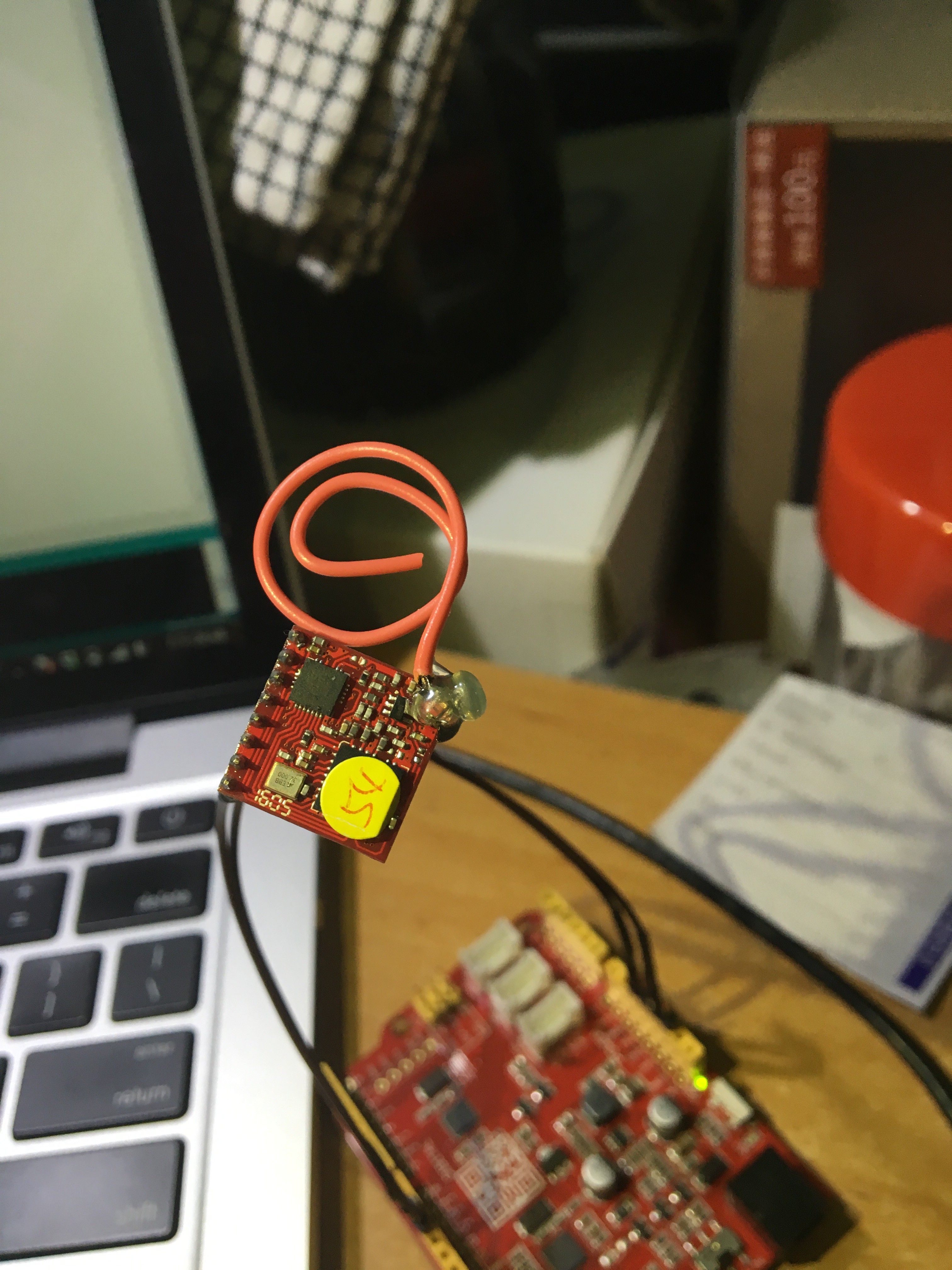
1.H/W 硬體連接方式.
- 利用3.3v的Arduino(Seedduino v4.2)的板子連接LORA MOdule
- 3.3V
- Gnd
- SW TX(Pin 10)
- SW RX(Pin 11)

2. S/W軟體在Arduino IDE上的訂義
//–已下為Arduino的程式//
#include <SoftwareSerial.h>
SoftwareSerial mySerial(10, 11); // RX, TX
void setup() {
// Open serial communications and wait for port to open:
Serial.begin(9600); //<-設定硬體UART的BaudRate為9600
while (!Serial) {
; // wait for serial port to connect. Needed for native USB port only
}
Serial.println(“HI The LORA is online now”);
// set the data rate for the SoftwareSerial port
mySerial.begin(115200); //<-設定軟體UART的Baudrate為115200(這是為了跟LORA module溝通所需要的Baudrate)
FunLora_0_GetChipID(); // 透過SW UART與LORA modue取得版本資料
delay(200);
FunLora_1_Init(); //透過SW UART對LORA Module作初始化。
delay(200);
FunLora_2_ReadSetup(); //讀取LORA Module初始化設定資料。
delay(200);
FunLora_3_Setup(3); //設定該LORA Module為接收模式, [ e.g FunLora_3_Stup(3)==>為接收\模式;FunLora_3_Stup(2)==>為發射模式 ]
delay(200);
FunLora_6_read(); //從LORA module Buffer 讀取資料。
delay(200);
Serial.println(“——-“);
FunLora_3_Setup(2); //設定該LORA Module為發射模式,[ e.g FunLora_3_Stup(3)==>為接收\模式;FunLora_3_Stup(2)==>為發射模式 。]
delay(200);
FunLora_5_write(); //從LORA module Buffer 寫入資料。
delay(200);
}
只要接線正確,應該就可以在你的Arduino IDE上看到正確的資料回應了。

對於Module所回應的資料有看不懂的地方,請檢查一下我們的UART command(命令)表!
- 該UART COMMAND table請在於購買後跟我們詢問!